Parts of a relay crossword – Step into the electrifying world of relays, where crossword enthusiasts can decipher the cryptic clues with ease. Our in-depth exploration of relay components will equip you with the knowledge to conquer any relay-themed crossword puzzle.
From the fundamental workings of a relay to its diverse applications, this guide delves into the heart of these essential electrical devices.
Relay Definition and Basic Operation

A relay is an electromechanical switch that uses an electromagnetic coil to control a set of electrical contacts. Relays are used to isolate electrical circuits and to control high-power circuits with low-power signals.
A relay consists of a coil, an armature, and a set of contacts. When the coil is energized, it creates a magnetic field that attracts the armature. The armature is connected to the contacts, which close when the armature is attracted to the coil.
When the coil is de-energized, the magnetic field collapses and the armature returns to its original position, opening the contacts.
Relay Components and Their Interactions
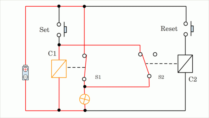
The following diagram shows the internal components of a relay and their interactions:

When the coil is energized, the magnetic field created by the coil attracts the armature. The armature is connected to the contacts, which close when the armature is attracted to the coil. When the coil is de-energized, the magnetic field collapses and the armature returns to its original position, opening the contacts.
Types of Relays
Relays come in various types, each with its own unique characteristics, advantages, and applications. The primary classification of relays is based on their construction, which can be electromechanical, solid-state, or hybrid.
Electromechanical Relays
Electromechanical relays are the traditional type of relays, consisting of a coil that generates a magnetic field when energized. This magnetic field actuates a movable armature, which in turn opens or closes contacts to control the flow of current in a separate circuit.
- Pros:High current-carrying capacity, long lifespan, cost-effective
- Cons:Mechanical wear and tear, slower switching speeds
Solid-State Relays
Solid-state relays (SSRs) use semiconductor devices, such as transistors or thyristors, to control the flow of current. They have no moving parts, making them more reliable and faster than electromechanical relays.
- Pros:Compact size, high switching speeds, no mechanical wear
- Cons:Lower current-carrying capacity, higher cost
Hybrid Relays
Hybrid relays combine the features of both electromechanical and solid-state relays. They use a solid-state device to amplify the input signal, which then actuates an electromechanical relay. This combination provides the benefits of both types, resulting in high current-carrying capacity, fast switching speeds, and increased reliability.
- Pros:High current-carrying capacity, fast switching speeds, increased reliability
- Cons:More complex design, higher cost
The table below summarizes the key differences between these relay types:
| Relay Type | Construction | Pros | Cons |
|---|---|---|---|
| Electromechanical | Coil and armature | High current-carrying capacity, long lifespan, cost-effective | Mechanical wear and tear, slower switching speeds |
| Solid-State | Semiconductor devices | Compact size, high switching speeds, no mechanical wear | Lower current-carrying capacity, higher cost |
| Hybrid | Solid-state and electromechanical components | High current-carrying capacity, fast switching speeds, increased reliability | More complex design, higher cost |
Relay Components

A relay is an electrically operated switch that uses a small amount of electrical power to control a larger amount of power. It consists of several essential components that work together to achieve this switching action.
The main components of a relay include the coil, contacts, armature, yoke, and terminals. Each component plays a specific role in the operation of the relay.
Coil
The coil is a copper wire winding that creates a magnetic field when an electric current flows through it. The magnetic field strength is directly proportional to the amount of current flowing through the coil.
The coil is usually made of copper wire because copper is a good conductor of electricity and has low resistance. The number of turns in the coil determines the strength of the magnetic field generated.
Contacts
The contacts are the switching elements of the relay. They are made of conductive material and are arranged in such a way that they can either make or break an electrical circuit.
The contacts are typically made of silver or gold because these metals have low resistance and are resistant to corrosion.
Armature
The armature is a metal piece that is attached to the contacts. When the coil is energized, the magnetic field generated attracts the armature, causing the contacts to move and change the state of the circuit.
The armature is usually made of iron or steel because these materials are strongly magnetic.
Yoke, Parts of a relay crossword
The yoke is a metal frame that supports the coil and the armature. It also provides a path for the magnetic flux generated by the coil.
The yoke is usually made of iron or steel because these materials are strongly magnetic.
Terminals
The terminals are electrical connections that allow the relay to be connected to an external circuit. The terminals are typically made of brass or copper because these metals have low resistance and are resistant to corrosion.
| Component | Function | Material |
|---|---|---|
| Coil | Creates a magnetic field when an electric current flows through it | Copper |
| Contacts | Make or break an electrical circuit | Silver or gold |
| Armature | Attached to the contacts and moves when the coil is energized | Iron or steel |
| Yoke | Supports the coil and the armature, and provides a path for the magnetic flux | Iron or steel |
| Terminals | Electrical connections that allow the relay to be connected to an external circuit | Brass or copper |
Relay Characteristics and Specifications
Relays possess specific characteristics that determine their functionality and suitability for various applications. These characteristics influence the selection and application of relays, ensuring optimal performance and reliability.
Coil Voltage
The coil voltage refers to the electrical potential required to energize the relay coil, causing it to create a magnetic field. This voltage can vary depending on the relay’s design and intended use. Relays are typically designed for specific coil voltages, such as 12V DC, 24V DC, or 120V AC.
Contact Rating
The contact rating specifies the maximum current and voltage that the relay contacts can safely handle without damage or excessive wear. It is essential to ensure that the relay’s contact rating is compatible with the load it will be switching.
Contact ratings are typically expressed in amperes (A) for current and volts (V) for voltage.
Switching Speed
The switching speed refers to the time it takes for the relay contacts to change state, from open to closed or vice versa. This characteristic is crucial in applications where fast switching is required, such as in electronic circuits or control systems.
To solve a relay crossword, you’ll need to identify the different parts of the puzzle. For example, the “move in the wind crossword” requires you to identify words that describe things that move in the wind. Once you’ve identified the different parts of the puzzle, you can start to solve it.
Switching speeds can vary significantly depending on the relay’s design and construction.
Isolation Voltage
The isolation voltage indicates the electrical potential difference that can be safely maintained between the relay’s coil and contacts. This characteristic is essential for ensuring electrical safety and preventing electrical hazards. Isolation voltages can range from a few hundred volts to several thousand volts, depending on the relay’s design and intended use.
| Characteristic | Definition | Typical Values |
|---|---|---|
| Coil Voltage | Electrical potential required to energize the relay coil | 12V DC, 24V DC, 120V AC |
| Contact Rating | Maximum current and voltage that the contacts can handle | 5A @ 250V AC, 10A @ 30V DC |
| Switching Speed | Time taken for the contacts to change state | Milliseconds to tens of milliseconds |
| Isolation Voltage | Electrical potential difference between coil and contacts | 500V, 1000V, 2500V |
Relay Applications: Parts Of A Relay Crossword
Relays find widespread use across various industries and sectors, playing a crucial role in automation, control systems, power distribution, and telecommunications. Their versatility stems from their ability to isolate electrical circuits, amplify signals, and perform logical operations.
Automation and Control Systems
- Industrial automation: Relays control machinery, conveyor belts, and robotic systems.
- Home automation: Relays automate lighting, security systems, and HVAC.
- Process control: Relays monitor and regulate temperature, pressure, and flow in industrial processes.
Power Distribution
- Circuit protection: Relays protect electrical circuits from overloads and short circuits.
- Load switching: Relays connect and disconnect heavy electrical loads, such as motors and transformers.
- Power factor correction: Relays optimize the power factor in electrical systems.
Telecommunications
- Signal routing: Relays switch and route telephone calls and data signals.
- Signal amplification: Relays amplify weak signals in communication systems.
- Line protection: Relays protect telecommunication lines from damage.
Relay Symbols and Diagrams

Relay symbols are standardized graphical representations used in electrical schematics and diagrams to denote relays. These symbols simplify circuit design and provide a clear understanding of the relay’s function and connections.
Relay Symbol Table
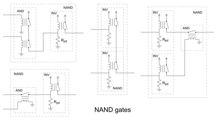
The following table lists commonly used relay symbols, their descriptions, and corresponding component names:| Symbol | Description | Component Name ||—|—|—|| [Image of relay symbol 1] | Single-pole, single-throw (SPST) relay | Normally open (NO) or normally closed (NC) || [Image of relay symbol 2] | Single-pole, double-throw (SPDT) relay | Changeover relay || [Image of relay symbol 3] | Double-pole, single-throw (DPST) relay | Two normally open (2NO) or two normally closed (2NC) contacts || [Image of relay symbol 4] | Double-pole, double-throw (DPDT) relay | Four-way relay |
Relay Ladder Diagrams
Relay ladder diagrams are a type of electrical schematic used to represent the logic and control of relay-based circuits. They use symbols to represent relays, switches, and other components, and they are arranged in a ladder-like structure.The interpretation of relay ladder diagrams follows these rules:
- Each horizontal line represents a circuit branch.
- Vertical lines represent connections between components.
- Input devices (e.g., switches) are connected to the left side of the ladder.
- Output devices (e.g., relays) are connected to the right side of the ladder.
- The flow of current through the ladder is from left to right.
Relay ladder diagrams are widely used in industrial automation and control systems. They provide a simple and intuitive way to represent complex relay-based circuits.
Relay Testing and Troubleshooting

Relay testing and troubleshooting are crucial for ensuring the proper functioning of relay systems. Regular testing helps identify potential issues early on, preventing costly failures and downtime.
Common testing methods include:
Continuity Checks
- Verify continuity between relay terminals and contacts using a multimeter.
- Check for open or short circuits that may prevent proper operation.
Coil Resistance Measurements
- Measure the resistance of the relay coil using a multimeter.
- Compare the measured value to the specified resistance to identify any deviations that may affect relay performance.
Contact Resistance Measurements
- Measure the resistance between relay contacts using a multimeter.
- High contact resistance can indicate wear or contamination, affecting relay switching capabilities.
Troubleshooting relay malfunctions involves a systematic approach to identify potential causes:
- Verify power supply to the relay.
- Check for loose connections or damaged wiring.
- Inspect relay contacts for wear or contamination.
- Test relay coil for continuity and proper resistance.
- Examine relay housing for any signs of damage or overheating.
Frequently Asked Questions
What is the primary function of a relay?
A relay acts as a switch, controlling the flow of electricity in a circuit.
How many types of relays exist?
Relays are classified into three main types: electromechanical, solid-state, and hybrid relays.
What is the purpose of the coil in a relay?
The coil generates a magnetic field when energized, which activates the relay’s contacts.